You settle into your living room, dim the lights to create a relaxing atmosphere, and suddenly, the silence is broken. It isn’t the rush of air conditioning or the distant traffic outside; it is a persistent, low-frequency drone emanating directly from your wall. This sound, a distinct $60\text{Hz}$ (or $50\text{Hz}$) oscillation, is the audible signature of electrical energy being converted into mechanical vibration. While a dimmer switch buzzing noise is undeniably frustrating, disrupting the ambiance the device was installed to create, it is also one of the most ubiquitous anomalies in residential electrical engineering.
Unlike standard single-pole toggle switches, which act as simple binary gates—physically making or breaking the circuit connection—dimmer switches are complex active components. They utilize semiconductor devices, typically TRIACs (Triode for Alternating Current), to rapidly chop the AC sine wave. This rapid switching occurs 120 times per second in a standard $60\text{Hz}$ electrical system. When you hear a light switch making buzzing noise, you are effectively hearing the physical components of the switch or the lighting load reacting to the stress of this rapid current modulation.
The immediate anxiety for any homeowner encountering this noise often centers on fire safety. Is the buzzing a symptom of arcing, a loose termination, or thermal runaway? The primary goal of this guide is to provide a rigorous technical framework for identifying the root cause of the noise, determining the safety profile of the installation, and executing a resolution. We will analyze the system variables, including the interaction between the dimmer’s phase-cutting technology (leading-edge vs. trailing-edge) and the capacitive or resistive nature of the bulb’s driver.
While silence is the gold standard for residential lighting, it is essential to understand that a very faint hum can sometimes be an inherent byproduct of the technology. Modern dimmers contain an inductor, known as a choke, designed to filter Radio Frequency Interference (RFI). As current flows through this coil, the magnetic field fluctuates, causing the ferrous core to expand and contract microscopically—a phenomenon known as magnetostriction. However, when this subtle operational hum escalates into an audible nuisance, the system is suffering from a compatibility mismatch, overload, or component failure. Through the following sections, we will isolate these variables to stop the noise and ensure your electrical system operates within safe thermal and acoustic limits.
To understand why do dimmer switches buzz, one must look beyond simple voltage reduction and examine the complex physics of modern solid-state electronics. Historically, older dimmers used variable resistors known as rheostats to dim lights. These devices lowered voltage by converting excess electrical energy into heat—a silent but highly inefficient process. Modern dimmers, however, utilize a completely different topology involving high-speed switching, primarily using a semiconductor device called a TRIAC (Triode for Alternating Current).
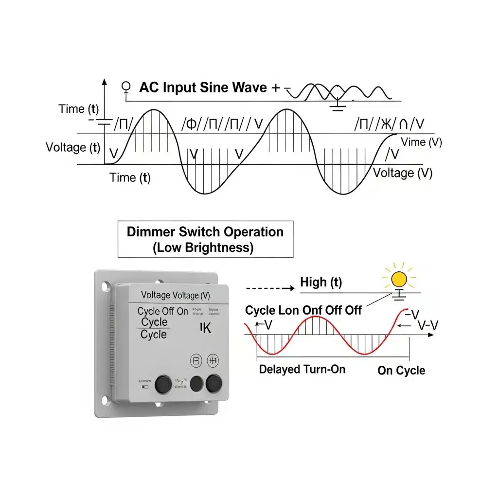
The fundamental operation of a modern dimmer is known as Phase-Fired Control or Phase-Cut Dimming. Rather than restricting the flow of electricity like a valve, the dimmer acts as a rapid-fire switch. In a standard North American household, the alternating current (AC) oscillates at a frequency of 60 Hz. This means the electrical sine wave crosses the zero-voltage point 120 times every second.
The dimmer circuit monitors these zero-crossings. To dim the light, the TRIAC "chops" the sine wave by delaying the conduction of current for a specific portion of each half-cycle. For example, to achieve 50% brightness, the dimmer waits until the AC wave reaches its peak before closing the circuit.
$$ f_{switching} = 60 \text{ Hz} \times 2 \text{ (half-cycles)} = 120 \text{ Hz} $$
This rapid switching occurs 120 times per second. When the TRIAC fires, the voltage spikes vertically from zero to the instantaneous line voltage. This results in a massive rate of change in current ($di/dt$) and voltage ($dv/dt$). It is this abrupt "turn-on" that generates the physical forces responsible for the noise.
The primary source of a dimmer switch humming is a component called the RFI (Radio Frequency Interference) choke. Because the rapid chopping of current generates significant electromagnetic interference that can disrupt radio and Wi-Fi signals, engineers install an inductor coil (the choke) to smooth the current rise time.
The choke consists of a copper coil wrapped around a ferrous (iron-based) core. As the current surges through the coil 120 times a second, it generates an intense, oscillating magnetic field. This field causes magnetostriction—a phenomenon where the ferrous core physically changes shape, expanding and contracting on a microscopic level in sync with the magnetic field. This physical vibration of the core moves air, creating the audible low-frequency buzz you hear.
The noise is not always confined to the switch box; often, users wonder, "why does my light switch buzz but the sound seems to come from the fixture?" The chopped waveform sent by the dimmer travels to the light bulb. In incandescent bulbs, the filament can vibrate due to the magnetic fields generated by the inrush current of each chopped cycle. In LED bulbs, which rely on internal drivers to convert AC to DC, the ceramic capacitors can exhibit a piezoelectric effect, vibrating physically when subjected to the harsh, chopped voltage waveform of an incompatible dimmer.
For homeowners encountering audible noise from their electrical fixtures, the primary concern is almost always fire safety. The short answer to " is a buzzing dimmer switch dangerous " is: usually not, but the distinction relies heavily on the specific characteristics of the sound and the accompanying physical symptoms. To understand the difference between a benign "nuisance buzz" and an active fire hazard, one must understand the electromechanical forces at play within the switch.
Standard phase-cut dimmers operate by chopping the AC sine wave, turning the voltage on and off rapidly—typically 120 times per second in a $60\text{Hz}$ system. This rapid switching creates a steep rise time in the voltage waveform, resulting in significant Radio Frequency Interference (RFI). To counteract this, manufacturers install an inductor (a choke coil) and a capacitor to filter the noise.
A buzzing light switch in a safe state is often suffering from magnetostriction. As current passes through the inductor coil, the magnetic field generates mechanical stress, causing the ferrite core or the copper windings to physically expand and contract slightly. This vibration occurs at the frequency of the mains supply ($60\text{Hz}$) or its harmonics ($120\text{Hz}$, $240\text{Hz}$, etc.). While annoying, this electromagnetic vibration is contained within the switch housing and poses no thermal threat to the structure.
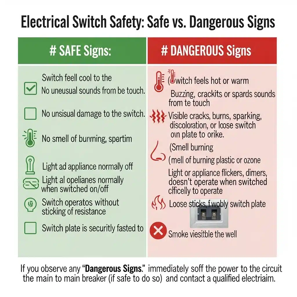
However, you must differentiate the rhythmic hum of an oscillating coil from the erratic crackle of an electrical fault. If your light switch buzzing is accompanied by any of the following symptoms, the switch must be isolated at the breaker immediately.
All dimmers generate some heat due to the internal resistance of the Triac (the semiconductor switch). However, if the switch plate is painful to touch or radiates significant heat, the dimmer is overloaded. The power dissipated as heat is defined by $P = I^2 R$. If the current ($I$) drawn by the bulbs exceeds the dimmer's rating, the heat generated can melt internal insulation, leading to a short circuit.
A clean, consistent hum is usually inductive. A sound that crackles, pops, or hisses indicates arcing. This occurs when electricity jumps across a gap in the circuit, ionizing the air. Arcing generates temperatures exceeding $10,000^\circ\text{F}$ ($5,500^\circ\text{C}$) at the microscopic point of contact. This is a primary cause of electrical fires.
If the arcing or overheating melts the polycarbonate casing of the switch or the PVC insulation of the wires, you will smell a distinct, acrid odor. A sharp, metallic smell indicates the creation of ozone ($O_3$) due to sustained arcing.
One of the most dangerous causes of a buzzing switch is a loose wire termination (screw terminal or wire nut). A loose connection increases the contact resistance ($R_{contact}$). According to Joule’s First Law, the heat generated at that specific point increases exponentially with the current.
$$ P_{heat} = I_{load}^2 \times R_{contact} $$
As the connection heats up, the metal expands; as it cools, it contracts. This thermal cycling loosens the connection further, increasing resistance and heat until the wire glows red hot, eventually igniting surrounding materials. If the buzzing sound changes pitch when you tap the wall plate, it is highly likely you have a loose termination that requires immediate professional attention.
While the audible noise from a dimmer often feels like an anomaly, it is usually a manifestation of mechanical resonance driven by electrical forces. To understand exactly why is my dimmer switch buzzing, one must look beyond the light bulb and examine the internal topology of the switch itself. The buzz is rarely random; it is a symptom of specific inefficiencies or mismatches within the electrical circuit.
The most technically significant cause of audible hum is exceeding the load rating of the semiconductor components, specifically the TRIAC (Triode for Alternating Current). Every dimmer has a maximum wattage rating, commonly $600W$ for standard residential incandescent dimmers, or $150W$ for CFL/LED equivalents.
However, this rating is not static. When dimmers are installed in a multi-gang box (side-by-side), the metal tabs—which function as heat sinks—must often be removed. This process, known as derating, significantly lowers the capacity of the switch.
For example, a standard $600W$ dimmer might follow this derating curve:
* Single Gang: $600W$ Max Load
* Double Gang (One side removed): $500W$ Max Load
* Triple Gang (Both sides removed): $400W$ Max Load
If the total power consumption ($P_{total}$) of your lighting array exceeds the derated capacity ($P_{rated}$), the TRIAC overheats, causing thermal stress and audible oscillation.
$$ P_{total} = \sum_{i=1}^{n} P_{bulb_i} $$
If $P_{total} > P_{rated}$, the internal components operate outside their safe thermal envelope, resulting in significant noise and potential failure.
A modern dimmer works by rapidly switching the current on and off—chopping the AC sine wave 120 times per second ($60 \text{ Hz} \times 2$). This rapid rise time ($di/dt$) generates substantial Radio Frequency Interference (RFI). To mitigate this, manufacturers install a choke coil (an inductor) consisting of copper wire wrapped around a ferrite core.
In high-end switches, this coil is "potted" (encased in epoxy or resin) to prevent movement. In cheaper models, the copper windings may be loose. As current pulses through the coil, the magnetic field expands and contracts, causing the wire to physically vibrate against the core. This phenomenon is often the primary reason behind dimmer buzzing. The noise is essentially the sound of the choke coil vibrating at twice the line frequency ($120 \text{ Hz}$).
Troubleshooting becomes more complex in 3-way or 4-way circuits (where lights are controlled from multiple locations). Standard mechanical 3-way switches are passive, but modern smart dimmers or electronic dimmers require precise synchronization.
If a master dimmer is paired with an incompatible remote switch, or if the "traveler" wires experience voltage drop, the phase-chopping timing can drift. This creates an unstable waveform sent to the fixture, causing the electronics in both the switch and the LED driver to resonate audibly.
Finally, if you are asking why does my dimmer switch buzz after years of silent operation, the culprit is likely mechanical or thermal fatigue.
* Carbon Track Wear: The potentiometer (the slider mechanism) utilizes a carbon track to determine resistance ($R$). Over time, friction wears this track down, causing inconsistent contact and micro-arcing.
* Relaxation of Windings: Years of thermal cycling—heating up during use and cooling down when off—can cause the previously tight windings on the RFI choke to loosen, introducing new vibration vectors.
Identifying whether the issue stems from an overload calculation, a low-quality dampening coil, or component aging is the first step toward permanently resolving the noise.
The transition from incandescent to Light Emitting Diode (LED) technology has fundamentally altered the electrical characteristics of residential lighting loads. While incandescent bulbs act as simple resistive loads, LEDs are complex, capacitive electronic loads driven by AC-to-DC converters. This mismatch between legacy dimming technology and modern drivers is the primary culprit behind led dimmer buzzing, a phenomenon rooted in the physics of phase-control dimming.
To understand why an LED hums, one must understand how the dimmer modulates power. Dimmers do not simply lower voltage; they rapidly switch the power on and off 120 times per second (in a 60Hz system) to lower the Root Mean Square (RMS) voltage delivered to the load.
Leading-Edge Dimmers (TRIAC/SCR):
Standard legacy dimmers use a Triode for Alternating Current (TRIAC). These switch the circuit on partway through the AC sine wave and turn off at the zero-crossing point. This creates a vertical rise in voltage at the firing angle $\alpha$.
Mathematically, the voltage delivered to the load is zero until time $t_1$, at which point it instantaneously jumps to the value of the grid voltage:
$$ V(t) = V_{peak} \sin(\omega t) \quad \text{for } t > t_1 $$
For a resistive incandescent bulb, this is harmless. However, an LED driver contains an input capacitor ($C$) to smooth voltage. The current flowing into a capacitor is defined by:
$$ I = C \frac{dV}{dt} $$
In a leading-edge dimmer, the rise time is near-instantaneous, causing $\frac{dV}{dt}$ to approach infinity. This results in a massive current spike every half-cycle. This repetitive surge causes mechanical vibration in the dimmer's internal choke coil and the LED driver's components, perceived as dimmer light switch buzzing.
Trailing-Edge Dimmers (ELV/MOSFET):
Modern dimmers designed for LEDs use transistors (MOSFETs or IGBTs) to switch the circuit on at the zero-crossing (where voltage is 0) and turn it off later in the wave. This eliminates the instantaneous voltage jump, keeping the $\frac{dV}{dt}$ low and preventing the current spike that agitates LED capacitors.
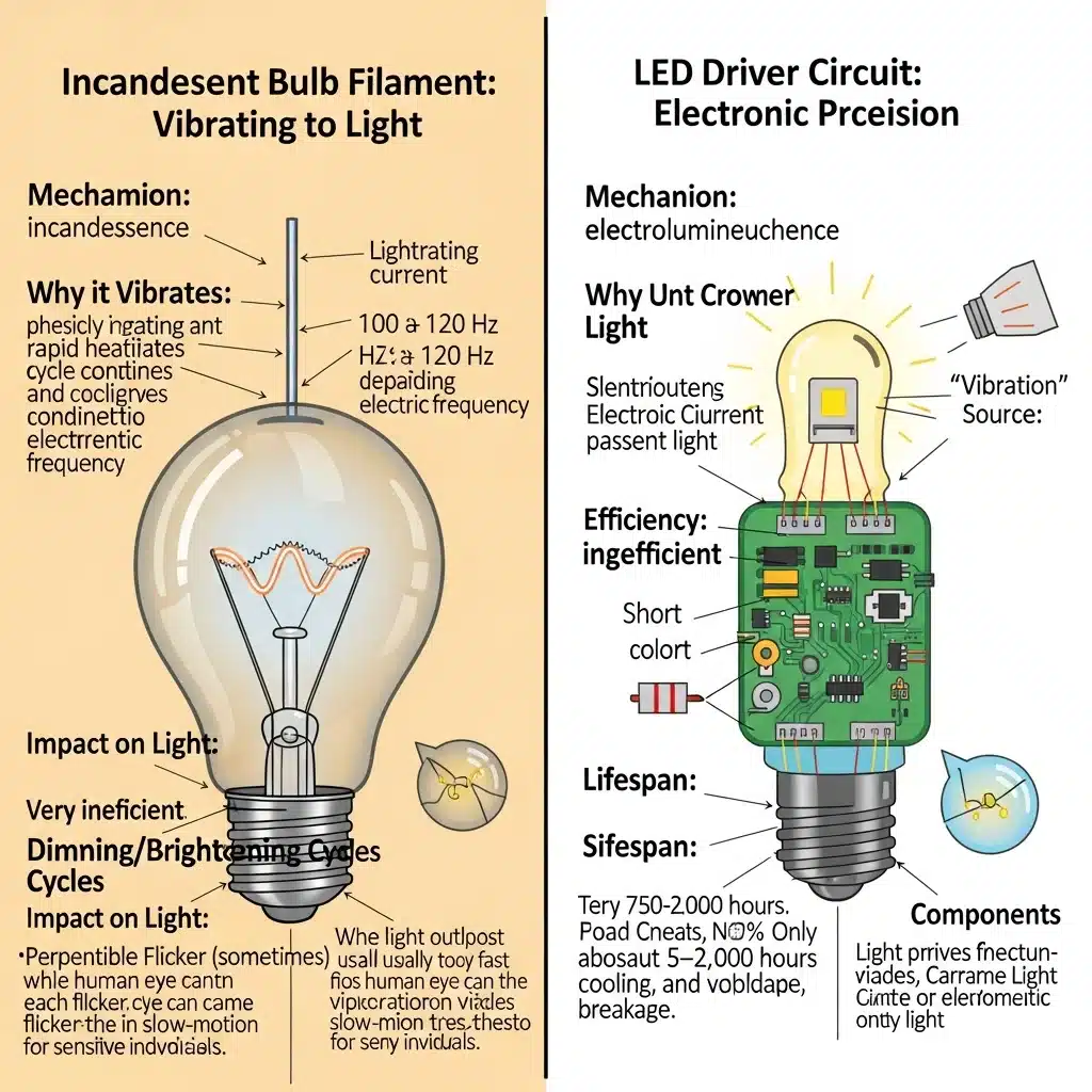
The source of the sound differs significantly depending on the bulb type. In incandescent bulbs, the filament acts as a resistive element. When subjected to the chopped waveform of a dimmer, the rapid changes in the magnetic field generated by the current cause the filament to vibrate thermally and magnetically. This "singing filament" is purely mechanical.
In LEDs, the noise is generated by magnetostriction and the piezoelectric effect.
1. Magnetostriction: The magnetic field inside the transformer or inductor of the LED driver changes shape slightly with the current flow, causing the ferrite core to expand and contract at 120Hz.
2. Piezoelectric Effect: Multi-layer ceramic capacitors (MLCCs) within the driver expand and contract when voltage is applied. If the frequency of this expansion matches the resonant frequency of the circuit board or housing, the entire bulb acts as a speaker membrane.
Using non-dimmable LEDs on a dimmer circuit is the most severe cause of auditory noise. A non-dimmable driver expects a constant sinusoidal AC input to rectify into DC. When the dimmer chops the wave, the driver attempts to draw current during the "off" periods of the phase cut, leading to rapid voltage oscillations.
This instability causes the TRIAC in the wall switch to lose its "holding current," causing it to misfire or turn off prematurely. The result is intense light bulbs buzzing and visible flickering. This is not merely an annoyance; the chaotic current draw creates excessive heat in the driver components, leading to catastrophic failure of the bulb or thermal damage to the dimmer switch itself.

Systematic dimmer switch troubleshooting requires isolating variables in the electrical circuit, starting with the load (the bulb) and moving toward the control mechanism (the switch) and infrastructure (wiring). A buzzing dimmer switch is rarely a phantom issue; it is almost always a symptom of component incompatibility, overload, or loose connections creating high-resistance faults. Follow this technical protocol to resolve the noise.
The most frequent cause of audible noise is a mismatch between the dimmer’s phase-cut topology and the LED driver’s power supply. Standard incandescent dimmers use Triac-based leading-edge phase cutting, which can cause the capacitors in non-dimmable or low-quality LED drivers to vibrate piezoelectrically.
To test this, remove all existing bulbs from the circuit. Install a single, high-quality, name-brand LED specifically labeled "Dimmable" (e.g., from the Philips WarmGlow or Cree Professional series). If the noise ceases, the previous bulbs lacked the internal circuitry required to smooth the chopped AC waveform.
Overloading a switch stresses the internal Triac or MOSFET components, causing thermal expansion and audible vibration. You must verify that the total wattage of the fixtures does not exceed the switch's rating. Note that dimmer switch buzzing often occurs when users confuse incandescent ratings with LED ratings.
Calculate the total power load ($P_{total}$) using the summation of individual bulb wattages ($P_{bulb}$):
$$ P_{total} = \sum_{i=1}^{n} P_{bulb_i} $$
Crucial Derating Logic:
If your dimmer is installed in a multi-gang box (side-by-side with other switches) and the metal heat-sink tabs have been removed to fit the faceplate, you must derate the switch capacity.
* 0 sides removed: Rated max (e.g., $600W$)
* 1 side removed: $\approx 83\%$ capacity (e.g., $500W$)
* 2 sides removed: $\approx 66\%$ capacity (e.g., $400W$)
Furthermore, verify the specific LED load rating. A dimmer rated for $600W$ incandescent/resistive load usually has a significantly lower maximum for CFL/LED capacitive loads, often capped at $150W$.
WARNING: Turn off the circuit breaker at the main service panel before proceeding. Verify zero potential with a non-contact voltage tester.
Loose electrical connections create high-resistance points. As current flows across this resistance, it generates heat and micro-arcing, which manifests as a distinct buzzing sound. Pull the switch from the junction box and inspect the side terminal screws or push-in backstab connections.
1. If "backstab" holes are used, remove the wires and relocate them to the side screw terminals. Backstabs are prone to spring fatigue over time.
2. Tighten side terminal screws to the manufacturer’s specified torque (typically 12–14 in-lbs).
3. Ensure the wire nut connecting the neutral wires (usually white) is tight; a loose neutral in the box can cause the entire circuit to hum.
If the load is calculated correctly and the wiring is secure, yet the dimmer switch buzzing persists, the switch itself is likely the failure point. Older rheostat or standard Triac dimmers cannot effectively manage the complex inductive and capacitive loads of modern lighting.
Replace the unit with a NEMA-compliant "C.L" (CFL/LED) dimmer. For low-voltage lighting systems (like track lighting), ensure you select an ELV (Electronic Low Voltage) or MLV (Magnetic Low Voltage) dimmer specifically matched to the transformer type. These modern switches often utilize trailing-edge phase control (Reverse Phase), which cuts the voltage on the descent of the sine wave rather than the ascent, drastically reducing the inrush current that causes filament and coil vibration.
Deciding between a Do-It-Yourself (DIY) repair and hiring a professional electrician requires a calculation of risk, technical competency, and direct financial outlay. While many dimmer switch problems stem from simple component incompatibility, the distinction between a nuisance noise and a hazardous electrical fault is not always audible.
For a standard single-pole application, the troubleshooting process is generally low-cost. If the issue is simply an incompatibility between the dimmer’s internal TRIAC (Triode for Alternating Current) and the LED driver, the cost is strictly material.
DIY Cost Breakdown:
* High-Quality Dimmable LED Bulbs: $\approx \$5 - \$8$ per unit.
* Universal/CL Dimmer Switch: $\approx \$25 - \$45$.
* Total Estimated DIY Investment: $C_{DIY} \approx \$30 - \$60$.
In contrast, hiring a licensed electrician involves a minimum service call fee, regardless of the job's simplicity. The cost function for professional remediation ($C_{Pro}$) can be modeled as:
$$ C_{Pro} = C_{Materials} + (R_{Labor} \times T_{Min}) $$
Where $R_{Labor}$ is the hourly rate (typically $\$80 - \$120$) and $T_{Min}$ is the minimum billable time (usually 1 to 1.5 hours). Consequently, a professional visit for a simple switch swap often yields a baseline cost of $150 to $250.
Ignoring the hum carries a potential cost that far exceeds the price of a service call. While magnetic resonance in a choke coil is benign, buzzing caused by resistive heating is a prelude to failure.
If the buzzing is caused by a loose wire termination, the contact resistance ($R_{contact}$) increases. According to Joule’s First Law, the power dissipated as heat ($P$) is defined as:
$$ P = I^2 \times R_{contact} $$
As resistance rises due to oxidation or loose torque, heat generation increases, leading to melted insulation, carbonization of the receptacle, and potential structure fires. In this context, the "cost" is the risk of property damage exceeding your insurance deductible (often $\$1,000+$), vastly outweighing the cost of a professional inspection.
While swapping a faceplate or bulb is within the realm of a homeowner, specific scenarios dictate immediate professional intervention to ensure code compliance and safety.
If your diagnostic process reveals scorched insulation or wiring that crumbles upon touch, cease all activity, isolate the circuit at the breaker panel, and engage a licensed electrician immediately.
While a low-decibel hum is often an inherent byproduct of phase-cut dimming technology, distinct changes in the audible frequency or volume can indicate dangerous electrical faults. It is critical to differentiate between the mechanical vibration of a choke coil and electrical arcing.
A light switch buzzing with a crackling or popping timbre usually indicates a loose wire termination or internal contact degradation. In electrical engineering terms, a loose connection reduces the contact surface area, significantly increasing resistance ($R$) at that point. According to Joule’s First Law, the power dissipated as heat ($P$) is proportional to the square of the current ($I$) multiplied by the resistance:
$$ P = I^2R $$
As resistance increases due to poor contact, thermal dissipation rises rapidly. If this heat exceeds the insulation's temperature rating, it causes melting, carbonization, and potentially an electrical fire. If the faceplate is warm to the touch (exceeding standard operating temperatures of $\approx 40^{\circ}C$ to $50^{\circ}C$) or if the sound is erratic, immediate replacement is required.
This phenomenon is directly related to the firing angle of the TRIAC (Triode for Alternating Current) within the dimmer assembly. Standard forward-phase (leading-edge) dimmers operate by "chopping" the AC sine wave. They wait for a specific duration after the zero-crossing point before switching the circuit "ON."
At 100% brightness, the full sine wave passes through with minimal interruption. However, at a 50% setting, the TRIAC fires exactly at the peak of the AC voltage waveform ($90^{\circ}$ or $\frac{\pi}{2}$ radians). This creates the steepest possible rise time ($dv/dt$) in voltage.
The rapid surge in current generates a sudden, intense magnetic field around the internal inductor (choke coil). This sudden magnetic expansion exerts the maximum mechanical force on the inductor's ferrous core and windings, causing the loudest audible vibration. As you dim further down or brighten up, the firing angle moves away from the voltage peak, reducing the suddenness of the electromagnetic impulse and quieting the noise.
Technically, almost all phase-cut dimmers generate some level of resonance, but high-quality units dampen this to an inaudible level. The sound usually originates from Magnetostriction. When the ferromagnetic core of the dimmer’s RFI (Radio Frequency Interference) filter is subjected to the rapidly changing magnetic fields caused by chopping the current, the core physically changes shape—expanding and contracting at twice the line frequency (120Hz in the US).
Budget dimmers often lack "potting"—the process of encapsulating electronic assemblies in a solid or gelatinous compound. Without potting, the copper windings on the toroid coil can vibrate against the core. Higher-end "reverse-phase" (trailing-edge) electronic dimmers use MOSFETs or IGBTs rather than TRIACs. These cut the waveform on the descent rather than the rise, resulting in a smoother transition and significantly less filament or component vibration.
Incompatibility is the leading cause of a dimmer switch buzzing when paired with LED loads. To ensure compatibility, you must match the dimmer topology to the LED driver's input impedance characteristics.