
The transition of commercial building automation from localized, analog broadcast control to globally networked, digital ecosystems fundamentally rests on standardized communication. When cross-disciplinary integrators or junior engineers ask, "what is DALI?", or more colloquially "whats a DALI driver?", the answer extends far beyond a basic acronym. To properly define DALI from an engineering standpoint: the Digital Addressable Lighting Interface is an international, open-standard, vendor-agnostic, bi-directional communication protocol explicitly engineered for professional commercial illumination, governed strictly by the IEC 62386 (and locally adapted standards such as GOST R IEC 62386) standard.
The core DALI definition establishes a unified digital language that allows micro-components—such as LED drivers, occupancy sensors, and localized application controllers—to interact seamlessly. By eliminating the proprietary vendor lock-in that historically crippled legacy systems, the protocol ensures multi-decade scalability. Its ubiquity is genuinely global; whether a high-end specification mandates the protocole DALI in European markets, or a localized contractor questions que es un DALI during a Latin American infrastructure bid, the underlying mathematical architecture, electrical constraints, and interoperability mandates remain universally identical. Understanding exactly what does DALI mean for a facility’s CAPEX and OPEX requires analyzing its absolute superiority over the analog systems it was designed to replace.
Legacy 0-10V and 1-10V systems are fundamentally unidirectional. A controller outputs a raw DC voltage, and connected fixtures blindly modulate their output based on that physical voltage level. This lack of telemetry makes systemic fault detection impossible. The transition to DALI completely redefines lighting control by utilizing digitally addressed, bi-directional frames encoded via precise Manchester encoding.
To clearly illustrate why commercial engineers universally specify DALI over legacy analog protocols, consider the following technical breakdown:
| Technical Parameter | Digital Addressable Lighting Interface (DALI-2) | Legacy 0-10V Analog | Engineering & Commercial Impact |
|---|---|---|---|
| Signal Modality | Bi-directional Digital (Manchester Encoded, 1200 baud) | Uni-directional DC Voltage variance | DALI natively supports fault logging (thermal, lamp failure) and real-time energy telemetry. 0-10V is blind. |
| Addressing Limits | 64 Control Gear + 64 Control Devices per Subnet | Not uniquely addressable; hardwired to zones only | DALI allows granular, software-defined grouping. 0-10V requires costly physical rewiring to change lighting zones. |
| Wiring Topology | Free-topology (Star, Tree, Line allowed). No closed loops. | Strict point-to-point or daisy chain. | DALI severely reduces conduit density and labor hours during the rough-in phase of construction. |
| Polarity Sensitivity | Insensitive (Internal bridge rectifiers handle inversion). | Highly Sensitive (Reversed polarity causes catastrophic dimming failure). | Massive reduction in post-installation troubleshooting and commissioning delays with DALI. |
| Dimming Curve | Computationally Logarithmic (Weber-Fechner physiological match). | Linear or hardware-dependent variable. | DALI guarantees synchronized, flicker-free deep dimming (<1%) across fixtures from completely disparate manufacturers. |
When evaluating what is a DALI network in practice, feedback from lead electrical installers highlights several distinct physical advantages that drastically reduce labor costs. Foremost is the protocol's high immunity to electromagnetic interference (EMI). Because DALI operates with a massive logic voltage gap—where a logical "High" rests near 16V DC and a "Low" is pulled down to 0V DC—minor induced voltages do not register as false commands.
Pro-Tip from the Field: Because of this EMI resilience, installers can completely eliminate dedicated, shielded low-voltage conduit. Standard practice dictates pulling a single standard 5-core mains cable (e.g., NYM-J 5x1.5mm²) containing Live, Neutral, Earth, DA+, and DA- within the exact same outer jacket. This single-pull method reduces copper costs and labor by up to 40% compared to isolating analog control lines.
However, field experience also reveals common engineering pitfalls regarding voltage drop. System designers must ensure that the maximum wire run between the DALI bus power supply and the furthest network node never exceeds 300 meters. The absolute legal voltage drop ($V_{drop}$) across the copper line must not exceed 2.0V to prevent the 16V nominal signal from degrading into the protocol's undefined "dead zone" (6.5V to 9.5V).
To calculate the maximum allowable run during the design phase, engineers utilize the standard voltage drop formula:
$$ V_{drop} = \frac{2 \cdot I \cdot \rho \cdot L}{A} $$
(Where $I$ is the max bus current of 0.25A, $\rho$ is the resistivity of copper $\approx 0.0175 \, \Omega \cdot mm^2/m$, $L$ is cable length, and $A$ is cross-sectional area).
Ultimately, understanding the true DALI meaning is recognizing that it transforms passive lighting fixtures into dense, mathematically verifiable nodes on an intelligent IT network.

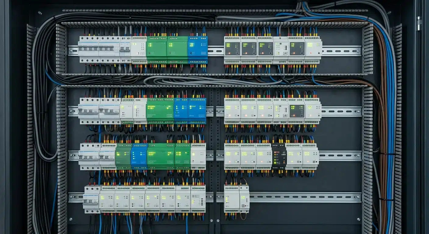
The physical and logical architecture of a modern dali lighting control system relies on a highly resilient, low-speed, high-voltage differential design. By stripping away the high-frequency fragilities of standard IT networks, the dali protocol achieves industrial-grade reliability directly alongside high-voltage mains AC.
The lifeblood of any dali system is the dali bus, an unshielded two-wire topology governed strictly by IEC 62386-101. Unlike traditional data protocols that require microvolt precision, DALI leverages massive voltage swings to guarantee signal integrity.
A dedicated bus power supply must maintain a nominal $16\text{V DC}$, with an absolute operational tolerance window of $11.5\text{V} \le V_{\text{bus}} \le 20.5\text{V}$. The strict short-circuit current limitation is $I_{\text{max}} = 250\text{mA}$. Given that standard control gear typically draws around $2\text{mA}$ as parasitic load, engineers must perform precise load-flow calculations during the design phase using the following threshold formula:
$$ I_{\text{total}} = \left( \sum_{i=1}^{64} I_{\text{gear}_i} \right) + \left( \sum_{j=1}^{64} I_{\text{device}_j} \right) \le 250\text{mA} $$
Signal transmission utilizes Manchester encoding at a rigid $1200\text{ baud}$ ($\pm 10\%$). This encoding method ensures a voltage transition in the middle of every bit, embedding the clock signal directly into the data stream and eliminating the need for a separate synchronization wire.
This intentional undefined "dead zone" between $6.5\text{V}$ and $9.5\text{V}$ grants the dali interface unparalleled immunity to electromagnetic interference (EMI). Data framing is mathematically asymmetric: the forward frame (from controller to gear) consists of 19 bits ($1$ start bit, $16$ data bits, $2$ stop bits) taking $15.8\text{ms}$. The backward frame requires only $8$ data bits, transmitting in $9.2\text{ms}$.
The historical transition from the first-generation standard to DALI-2 fundamentally redefined the capability of the dali control system.
Under dali 1 (originating from IEC 60929), only the downstream control gear (LED drivers, ballasts) was standardized. Input devices like sensors were strictly proprietary. Consequently, an engineer specifying a dali lighting system was locked into single-master architectures; the central controller acted as an isolated dictator, continuously polling dumb sensors and creating massive bus latency.
DALI-2 (IEC 62386 Part 103) shattered this limitation by standardizing control devices. Modern DALI-2 architectures utilize event-driven, multi-master logic. A localized sensor processes motion and independently dispatches an asynchronous dali program event frame to the bus. Multiple application controllers can listen simultaneously and react without data collisions, fundamentally decentralizing the network intelligence.
| Parameter / Standard Feature | Legacy dali 1 (IEC 60929) | Modern DALI-2 (IEC 62386) | Engineering Impact |
|---|---|---|---|
| Control Device Standardization | None (Proprietary only) | Fully standardized (Part 3xx) | Allows mixing sensors/switches from disparate manufacturers (e.g., Osram drivers with Zencontrol sensors). |
| Bus Architecture | Single-Master (Polling) | Multi-Master (Event-driven) | Eliminates polling latency; drastically improves response times in dense sensor grids. |
| Address Space | 64 Control Gear only | 64 Gear + 64 Control Devices | Doubles absolute node capacity per subnet without sacrificing luminaire addresses. |
| Interoperability Testing | Manufacturer Self-Declaration | Independent DiiA rigorous testing | Eradicates edge-case bugs and ensures true plug-and-play field integration. |
| Fade Time Resolution | Limited to fixed steps | Extended ($0.1\text{s}$ up to $16\text{ minutes}$) | Essential for high-end architectural and biological Human-Centric Lighting fading. |
Despite theoretical tolerances, integrating a large-scale dali system exposes distinct physical realities that commissioning engineers must preempt.
Pro-Tip from the Field: While IEC regulations allow up to $300\text{m}$ of bus length, real-world copper capacitance limits this. Installers frequently note that running standard $1.5\text{mm}^2$ wire to the $300\text{m}$ threshold introduces a voltage drop ($\Delta U$) that dangerously flirts with the $11.5\text{V}$ idle minimum. Best practice in accordance with GOST R 50571.5.52 is to limit subnets to $250\text{m}$ maximum, or up-size to $2.5\text{mm}^2$ core geometries if long linear runs in warehouses are unavoidable.
Common Installer Feedback:
The strict component taxonomy defined by the IEC 62386 standard (and its regional equivalents, such as GOST R IEC 62386) bifurcates the physical DALI network into two distinct operational domains: Control Gear (the execution layer) and Control Devices (the sensory and logic layer). Mastering this segregation is critical for engineering robust dali electronics that comply with rigorous international electrical installation rules, including the European HD 384 and the CIS region's ПУЭ (Rules for Electrical Installation), which dictate permissible cable routing and interference mitigation.
Control gear represents the muscular output of the system. In modern architectures, this is almost exclusively the dali led driver (or dali treiber, as frequently referenced in the highly influential DACH engineering market). These devices ingest digital Manchester-encoded frames and physically execute Pulse Width Modulation (PWM) or Constant Current Reduction (CCR) to manipulate luminaire output.
When selecting a dali driver, engineers must decide between Device Type 6 (DT6) and Device Type 8 (DT8) topologies based on the project's Human-Centric Lighting (HCL) requirements. A standard DT6 driver requires a distinct DALI short address for every physical LED channel. Conversely, a DT8 driver utilizes a single address to mathematically abstract complex multi-channel color mixing (Tunable White or RGBWAF) directly on the driver's microprocessor.
| Specification Parameter | Osram OTi DALI (DT6 - Part 207) | Tridonic premiumCCT (DT8 - Part 209) |
|---|---|---|
| Addressing Efficiency | Low (1 Address per color channel) | High (1 Address for total CCT/RGB control) |
| System Scale limits | Max 32 Tunable White fixtures per subnet | Max 64 Tunable White fixtures per subnet |
| Fade Synchronization | Software-dependent (risk of color shift) | Hardware-native (perfectly linear color transitions) |
| Typical Lifespan (@ $T_c \le 75^\circ$C) | ~100,000 Hours | ~100,000 Hours |
| Relative Cost per Node | Baseline | +20% to +35% Premium |
| Best Application | Monochromatic general illumination | Circadian lighting, high-end architectural |
Unlike legacy proprietary protocols, DALI-2 rigorously standardizes the intelligence of the network. This category is subdivided into Application Controllers and Input Devices.
A central dali controller (such as the WAGO 753-647 or Helvar 905) dictates the overarching logic. It evaluates environmental telemetry and manual overrides to orchestrate the dali controls across the entire bus. In a multi-master DALI-2 topology, multiple application controllers can operate asynchronously without packet collision.
Feeding data to these controllers are the input devices, which operate in an event-driven mode to conserve the strictly limited 1200 baud bandwidth. A standard dali sensor (Part 303/304, handling occupancy and lux levels) or a physical dali switch (Part 301/302 push-buttons) will only transmit a frame when an environmental delta occurs. Because these devices frequently draw parasitic power directly from the DALI bus rather than a dedicated mains connection, engineers must rigorously calculate the total bus load using the formula:
$$ N_{devices} = \sum_{i=1}^{n} I_{draw(i)} \le I_{bus\_supply} $$
Where $I_{bus\_supply}$ is strictly limited to 250 mA. If an installation incorporates dozens of dali switches and multi-sensors, the parasitic draw can easily exceed the power supply limit long before reaching the mathematical 64-device limit.
Pro-Tip: Always verify the Guaranteed Bus Power vs. Maximum Bus Power. A DALI power supply might guarantee 200 mA but cap at 250 mA. If your combined dali drivers (typically ~2 mA each) and input devices (which can draw 5-15 mA each) exceed the guaranteed threshold, the network will suffer from intermittent, highly difficult-to-diagnose voltage droops, leading to dropped frames and "ghost" switching.
Field integrators consistently highlight that mixing DALI-1 and DALI-2 hardware on the same physical bus is the primary source of commissioning delays.

To definitively answer what is dali dimming and how dali dimming works at a purely engineering level, one must examine the computational psychophysics embedded within the IEC 62386 standard. Unlike primitive voltage-gated protocols, a true digital dali dimming system mathematically normalizes the physical photon output of a dali led driver to directly align with human biological perception.
Human visual sensitivity to brightness is intrinsically non-linear; it strictly follows a logarithmic function defined by the Weber-Fechner law:
$$ P = k \cdot \ln\left(\frac{S}{S_0}\right) $$
where $P$ represents perceived brightness, $S$ is measured physical luminance, and $S_0$ is the absolute threshold of visual perception.
In a standard dali dimmable fixture, the native fade profile utilizes an 8-bit signal space (255 discrete digital steps) to achieve a highly calibrated logarithmic dimming curve. At the extreme lower bounds (e.g., 0.1% to 10%), the physical electrical current to the dali lamp scales precisely in micro-increments. This architecture mathematically eliminates the visible "stepping" or "popcorning" anomalies notorious in legacy 0-10V arrays. The exact physical output $X(n)$ for a given digital step $n$ (from 1 to 254) in a logarithmic dali dim profile is computed as:
$$ X(n) = 10^{\frac{n-1}{253} \cdot \log_{10}(1000)} / 10 $$
However, control engineers must actively reprogram drivers to a Linear curve when integrating with specific external BMS gateways (e.g., KNX or BACnet) that naturally apply their own logarithmic scaling. If both the gateway and the luminaria dali operate logarithmically, a critical "double logarithmic" error occurs, aggressively compressing the mid-range fade and completely destroying the architectural lighting intent.
When drafting the dali dimming wiring schematics for enterprise-grade dali lighting, the protocol’s defining advantage is structural forgiveness. The bus relies on a 16V DC nominal supply ($11.5V$ to $20.5V$ operational tolerance) strictly capped at 250mA.
DA+ and DA- interchangeably. This feature eradicates cross-wiring faults during rapid commercial deployments.| Technical Parameter | DALI Dimming (Log/Linear) | Analog 0-10V Control | Phase-Cut (Triac) |
|---|---|---|---|
| Protocol Architecture | Bi-directional Digital (Manchester encoded) | Uni-directional Analog Voltage | AC Sine-wave manipulation |
| Dimming Resolution | 0.1% - 100% (High-resolution, seamless fade) | 10% - 100% (High risk of flicker at low bounds) | 5% - 100% (Highly dependent on load matching) |
| Cabling Requirements | 2-core unshielded, polarity-free ($1.5\text{ mm}^2$) | 2-core polarity sensitive, shielded pref. | No extra control wires (Mains copper only) |
| Topology Constraints | Free topology, max 300m, 64 nodes per subnet | Daisy-chain, voltage drop dictates limits | Point-to-point hardwired to local switch |
| Data & Fault Telemetry | Native (Thermal, lamp failure, energy logging) | None (Blind operation) | None (Blind operation) |
| Relative Cost-to-Scale | Moderate initial, Extremely low maintenance | Low initial, High maintenance | Low initial, Restrictive lifecycle scaling |
Pro-Tip: When defining what is dali lighting to global stakeholders (whether it is specified as dali licht in DACH engineering packages or dali éclairage in Francophone specifications), immediately emphasize the CAPEX savings of 5-core integrated cabling. Running Mains (L, N, E) and Control (DA+, DA-) within a single standard 5-core cable bypasses the need for segregated data conduits, regularly cutting conduit labor costs by up to 40%.
Based on rigorous real-world commissioning logs and direct installer feedback, relying purely on basic standard compliance can still lead to site delays. Systems integrators frequently report immense hidden advantages when specifying premium-tier hardware (such as Tridonic EXCITE or Osram OTi DALI intelligent drivers) over generic DALI-compliant imports. High-end drivers feature meticulously refined PWM translation algorithms that support entirely flicker-free, sub-1% deep dimming out of the box, whereas budget drivers often introduce a harsh "snap-to-off" threshold below 3% output.
Common Field Pitfall: The most frequently reported localized failure in complex dali lights installations involves electrical contractors substituting standard $0.75 \text{ mm}^2$ or $1.0 \text{ mm}^2$ gauge wire for the control bus to reduce raw material expenditure. While this thinner gauge performs perfectly in a short factory test rig, during physical deployment, the compounding factors of bus capacitance and extreme voltage drop over 150+ meters inherently induce intermittent Manchester data packet loss. The furthest fixtures on the line will unpredictably drop out of digital network discovery or fail to execute group Scene commands. Professional design engineers must explicitly mandate the $1.5 \text{ mm}^2$ standard directly in the issued IFC (Issued For Construction) drawings to mitigate this exact liability.
Designing robust dali lighting controls mandates strict adherence to the mathematical boundaries of the IEC 62386 standard. Unlike IP-based networks, a standard wired DALI subnet is physically and logically constrained. The fundamental architectural equation governing a single DALI bus dictates two distinct address pools:
$$N_{gear} \le 64 \quad \text{and} \quad N_{device} \le 64$$
Where $N_{gear}$ represents control gear (LED drivers, relays) and $N_{device}$ represents control devices (sensors, application controllers).
Beyond addressing, electrical engineers must calculate the parasitic current draw to ensure the dedicated bus power supply is not overloaded. The protocol strictly limits maximum bus current to 250 mA to protect the control logic. The cumulative current of all attached nodes must satisfy:
$$\sum_{i=1}^{n} I_{gear\_i} + \sum_{j=1}^{m} I_{device\_j} \le 250 \text{ mA}$$
Typical DALI control gear draws $\approx 2 \text{ mA}$, while a multi-sensor (e.g., PIR + Lux) might draw $10 \text{ mA}$ to $15 \text{ mA}$.
To calculate the maximum permissible cable length, engineers must account for the maximum allowable voltage drop ($\Delta V_{max} = 2.0\text{V}$) across the bus at nominal 16V DC. Utilizing the formula for DC voltage drop:
$$\Delta V = \frac{2 \cdot L \cdot I \cdot \rho}{S} \le 2.0\text{ V}$$
Where $L$ is length, $I$ is total bus current, $\rho$ is the resistivity of copper ($0.0175 \ \Omega \cdot \text{mm}^2/\text{m}$), and $S$ is the cross-sectional area. For a standard $1.5\text{ mm}^2$ cable at maximum load, this mathematically restricts the furthest node to exactly 300 meters from the power supply. Per local wiring standards such as ПУЭ (Rules for Electrical Installation) and GOST R IEC 62386, DALI’s high immunity allows routing low-voltage data parallel to 230V mains in standard 5-core cabling (e.g., VVGng-LS 5x1.5) without interference, significantly reducing material expenditure.
While macro-level dali lighting control dictates room-wide routing, the D4i extension transforms individual fixtures into self-contained IoT hubs. D4i relies on four specific extensions:
| Protocol / Standard | Data Type | Topology | Wiring Polarity | Dimming Curve | Diagnostic Telemetry | Cost Per Node |
|---|---|---|---|---|---|---|
| DALI / DALI-2 | Bi-directional Digital | Free (Tree, Star, Line) | Insensitive (Auto-rectified) | Logarithmic (Standard) | Deep (Energy, Thermal, Lamp fault) | Moderate |
| 0-10V / 1-10V | Uni-directional Analog | Point-to-Point / Daisy | Sensitive (Prone to fail) | Varies by manufacturer | None | Low |
| TRIAC (Phase-cut) | Mains Voltage Alteration | Daisy-chain | N/A (Mains Live/Neutral) | Poor (Flicker < 15%) | None | Very Low |
| DMX512 | Uni-directional Digital | Strict Daisy-chain | Sensitive + Termination | Linear (High refresh) | Minimal (Requires RDM) | High |
| KNX | Bi-directional Digital | Free Topology | Sensitive | Dependent on actuator | Comprehensive | Very High |
Pro-Tip from the Field: Integrators deploying premium Osram or Tridonic DALI-2 drivers frequently praise DALI's polarity-free wiring. In a standard 500-fixture office deployment using legacy 0-10V, field feedback consistently shows that $3-5\%$ of fixtures fail upon initial commissioning due to crossed positive/negative control wires, requiring costly ceiling reopening. DALI mathematically eliminates this physical layer error. However, commissioning DALI networks requires specialized hardware interfaces (e.g., Lunatone DALI USB, WAGO 753-647 modules) and trained programmers, shifting the labor cost from the physical electrical installation phase directly to the IT software configuration phase.

Particularly in Northern Europe, where high-end commercial dali lysstyring (lighting control) and broader dali styrning (DALI control) integrations are mandated by strict energy directives such as EN 15193, system integrators possess deep, pragmatic insights into what happens when theoretical protocol specifications meet physical construction sites. Field experience routinely dictates that the operational success of a DALI-2 network is determined not just by the quality of the silicon, but by disciplined physical installation and nuanced gateway configuration.
The most universally celebrated installer feedback regarding the physical layer is the absolute relief of polarity-insensitive wiring. In legacy analog 0-10V architectures, a single reversed pair of control wires by an electrical contractor could compromise an entire lighting zone, requiring massive labor expenditure to trace and rectify. Because standard DALI control gear utilizes internal bridge rectifiers, the $D+$ and $D-$ lines can be swapped arbitrarily at any node without fault. Integrators consistently report that this localized error-proofing reduces commissioning delays by up to $15-20\%$ on large-scale enterprise deployments.
However, real-world reviews frequently highlight a critical pitfall: capacitance limits. While the standard allows for 300-meter cable runs, installers who ignorantly utilize incorrect cable types often induce signal degradation.
Pro-Tip: The IEC 62386 standard dictates a maximum voltage drop of $2.0\text{ V}$ and a maximum bus capacitance of $250\text{ nF}$. The formula for voltage drop is critical during the engineering phase:
$$\Delta V = \frac{2 \cdot L \cdot I_{max} \cdot \rho}{A} \le 2.0 \text{ V}$$
Where $L$ is length, $I_{max}$ is $0.25\text{ A}$, $\rho$ is copper resistivity, and $A$ is the cross-sectional area. Integrators using cheap, highly capacitive shielded cables near high-voltage switchgear frequently experience inductive data corruption despite being well under the 300-meter limit.
While the 24-bit random addressing sequence is mathematically elegant, real-world field experience reveals occasional "ghosting" or addressing collisions. The mathematical probability of two devices generating the exact same random address out of $M = 16,777,215$ possibilities for $n = 64$ devices is statistically trivial, governed by the birthday paradox adaptation:
$$P(\text{collision}) = 1 - \prod_{i=1}^{n-1} \left(1 - \frac{i}{M}\right) \approx 0.00012$$
or roughly $0.012\%$.
Yet, integrators frequently report collisions. This is almost exclusively traced back to poorly coded firmware in budget-tier control gear where the pseudo-random number generator (PRNG) seed is identical across a manufacturing batch, or extreme electromagnetic interference (EMI) corrupting the binary search replies. When this occurs, addressing tools like the Tridonic masterCONFIGURATOR or Lunatone DALI Cockpit become indispensable. Experienced specialists manually trigger a localized WITHDRAW command to isolate misbehaving drivers and utilize the physical "WINK" function to visually confirm spatial locations before manually writing the Short Address directly to the driver's non-volatile memory via a USB-to-DALI interface.
When scaling beyond a single 64-device subnet, the integration of DALI into overarching ANSI/ASHRAE 135 (BACnet) Building Management Systems introduces a severe bottleneck: polling saturation. Because the DALI bus operates at a sluggish 1200 baud rate, tying it directly to a BACnet/IP network operating at 1 Gbps creates a massive data-rate mismatch.
Integrators often mistakenly configure the central BMS to continuously poll individual DALI nodes for D4i diagnostic data. This immediately overloads the DALI gateway’s buffer, leading to dropped frames, unresponsive luminaires, and catastrophic field reviews. Best practices dictate that the gateway must be configured to utilize Change of Value (COV) subscriptions, where the gateway only pushes data to the BMS when a significant event occurs, strictly protecting the limited DALI bandwidth.
| Gateway Model / Series | Architecture Modality | Polling Buffer & Traffic Control | Integrator Feedback & Real-World Reliability |
|---|---|---|---|
| Loytec L-DALI (e.g., ME204) | Standalone IP Router (Multi-Line) | Exceptional. Native BACnet COV generation; robust AST capabilities onboard. | The gold standard for enterprise IT/OT convergence. Highly reliable, though the web-based UI possesses a steep learning curve. Excellent for large airport/hospital topologies. |
| WAGO 750-641 | Modular PLC Master | Managed via CoDeSys logic; requires manual buffering configuration. | Incredibly scalable and cost-effective per node. Installers warn that it requires advanced PLC programming expertise. If programmed poorly, BACnet polling will easily crash the DALI loop. |
| Intesis DALI-BACnet (INBACDAL) | Point-to-Point Converter | Limited localized buffer. Translates absolute values, lacks deep D4i parsing. | Excellent for rapid, small-scale retrofits. Field reviews note it struggles under heavy data loads if high-density occupancy sensors are continuously triggering. |
To achieve maximum lifecycle reliability, field engineers strongly advocate for the deployment of intelligent, edge-computing gateways (like the Loytec L-DALI). By pushing the logic down to the gateway rather than relying on a centralized BMS server to make micro-second lighting decisions, the facility ensures that if the corporate IT network goes offline, the localized dali lysstyring architecture continues to operate autonomously, executing local sensor logic and maintaining absolute life safety compliance.
The justification for upgrading a facility's physical infrastructure from legacy analog systems to a comprehensive dali control ecosystem relies entirely on shifting the financial analysis from Initial Capital Expenditure (CapEx) to Total Cost of Ownership (TCO). While the hardware costs for DALI-2 and D4i-certified luminaires typically command a 15–25% premium over standard 0-10V equivalents, the robust telemetry generated by the IEC 62386 architecture fundamentally alters Operating Expenditure (OpEx). In enterprise deployments, the Return on Investment (ROI) is generally realized within 18 to 36 months, driven primarily by automated life-safety compliance, aggressive energy auditing, and predictive asset management.
To accurately model this financial recovery, engineers utilize the following continuous payback formulation:
$$ ROI = \left( \frac{\sum (E_{savings} + M_{savings} + L_{savings}) - C_{capex}}{C_{capex}} \right) \times 100 $$
Where $E_{savings}$ represents granular energy curtailment, $M_{savings}$ denotes the reduction in replacement hardware via predictive maintenance, and $L_{savings}$ equals the direct labor offset from automated diagnostics, particularly emergency light testing.
Historically, achieving building-wide energy auditing required the installation of expensive external Current Transformers (CTs) and secondary power meters at the distribution board level. Under the D4i extension, Part 252 natively mandates that the LED driver (such as the eldoLED SOLODrive or Osram Optotronic Intelligent series) continuously calculates and logs its own active power ($W$) and apparent energy ($Wh$) directly on the silicon.
This hyper-localized energy telemetry allows Building Management Systems (BMS) to dynamically generate compliance reports for strict environmental standards like ASHRAE 90.1, LEED v4, or BREEAM without any supplementary hardware.
Simultaneously, Part 253 (Diagnostics & Maintenance) transitions facility operations from reactive "run-to-failure" models to highly predictive maintenance. The DALI driver monitors critical physical metrics:
Pro-Tip for Integrators: When mapping D4i data into a centralized BMS via a gateway (e.g., Loytec LDALI-ME204-U or WAGO 753-647), do not set the system to poll Part 252 energy data asynchronously at high frequencies (e.g., every 5 seconds). The 1200-baud DALI bus will immediately bottleneck, causing severe latency in standard lighting commands. Poll energy data globally every 15 minutes, while utilizing event-driven flags for critical Part 253 hardware failures.
The most profound, immediate financial return of a DALI network lies in the automation of Emergency Lighting (Device Type 1). Regional fire safety codes (such as EN 50172 in Europe, GOST IEC 60598-2-22, or NFPA 101 in North America) legally mandate routine functional and full-duration discharge testing of emergency luminaires.
In a standard building with 1,000 emergency fixtures, manual testing requires technicians to physically interrupt circuits, trigger a stopwatch, visually verify output for 1-3 hours, and manually log the data. DALI automates this entirely. The BMS triggers the Command 227 (Start Duration Test), the drivers autonomously discharge and monitor their internal battery voltage curves, and the gateway automatically collates the results (Pass, Battery Failure, Lamp Failure) into a digitally signed compliance ledger.
| System Architecture | Fault Isolation & Diagnostics | Energy Metering Modality | Emergency Testing Labor (1,000 Nodes/Yr) | Est. Hardware CapEx per Node | Est. Maintenance OpEx/Yr |
|---|---|---|---|---|---|
| Legacy 0-10V Analog | Visual inspection only (Reactive) | External CTs required at panel | ~300 Man-Hours (Highly Disruptive) | \$45.00 | \$12,500 | |
| Basic DALI-1 | Basic lamp/gear failure flags | Calculated via estimated output | Automated (If DT1 equipped) | \$65.00 | \$4,200 | |
| DALI-2 / D4i Ecosystem | Real-time thermal, voltage, L80 tracking | Native Part 252 silicon metering | Zero direct physical labor | \$85.00 | < \$1,500 |
Feedback from tier-one commercial integrators consistently highlights a massive hidden advantage of D4i's Part 251 (Luminaire Data/Memory Bank 1).
When engineering a lighting backbone, selecting the appropriate control routing tier is critical. Below is a comparative analysis of primary control deployment strategies utilized in modern BMS integrations.
| Parameter | Legacy DALI-1 Controller | DALI-2 Multi-Master Gateway (e.g., WAGO 753-647) | DALI+ Thread Router (e.g., zencontrol Wireless) |
|---|---|---|---|
| Standard / Compliance | Early IEC 62386 (Self-certified) | IEC 62386 Part 101/103 (DiiA Tested) | DALI+ over Thread (IPv6) |
| Network Architecture | Polled (Single Master dictates all) | Event-driven (Multi-Master, asynchronous) | Wireless IP Mesh (Self-healing) |
| Addressing Limits | 64 Gear (Sensors use proprietary logic) | 64 Gear + 64 Control Devices per subnet | Virtually unlimited (IPv6 address space) |
| BMS Integration | Often requires proprietary translation | Direct mapping to BACnet/KNX via gateway | Native IT network integration (REST API/MQTT) |
| Avg. Hardware Cost | Low ($100 - $200 per node) | Medium ($300 - $600 per gateway panel) | High ($80+ per luminaire embedded node) |
| Ideal Application | Small, isolated legacy retrofits | Large commercial buildings, heavy BMS synergy | High-end architectural retrofits, hard-to-wire ceilings |
Pro-Tip from the Field: "While the standard permits up to 300 meters of cable length, field engineers frequently encounter intermittent data dropouts when combining maximum cable runs with thin-gauge wire and a fully loaded bus drawing near 250mA. Always calculate your voltage drop."
Critical Installer Pitfalls & Solutions: