
You have likely arrived here after a frustrating specific sequence of events: you purchased a modern home automation device, cut the power at the breaker panel, and removed the faceplate of your existing toggle switch. You expected to see the standard four-wire configuration required by most WiFi devices: a Line (Hot), Load, Ground, and a bundle of white Neutral wires tucked into the back of the electrical box.
Instead, you found a wiring configuration that defies the instruction manual: a simple two-wire setup (usually black and white, or two blacks) connected directly to the switch terminals, plus a bare copper ground. This specific absence of a return path is known as having no neutral wire, and it presents a fundamental circuit theory challenge for standard smart home hardware.
This situation is standard for residential structures built prior to the mid-1980s. Before the National Electrical Code (NEC) was updated (specifically NEC 404.2(C) in 2011) to mandate neutral conductors in most switch boxes, electricians utilized a wiring topology known as a Switch Loop. In a switch loop, the branch circuit power ($120V_{AC}$) runs directly from the panel to the ceiling light fixture first. A single 14/2 or 12/2 Romex cable is then run down to the wall switch to interrupt the "Hot" line.
In this legacy configuration, the white wire connected to your switch is not a neutral. It is actually a "hot" wire carrying current down from the fixture (Line) or back up to the light (Load), often unmarked by the requisite black electrical tape. Because a standard single-pole, single-throw (SPST) mechanical switch is a passive device that simply opens or closes the circuit, it requires no power to operate. Mathematically, when the mechanical switch is open, the current $I = 0$, and power consumption is zero.
However, a smart switch is an active load. It contains a microcontroller unit (MCU), a radio transceiver (WiFi, Z-Wave, or Zigbee), and a relay or triac for dimming. To function, the switch requires a continuous power supply, governed by the equation $P = V \times I$. Without a neutral wire to complete the circuit back to the panel effectively bypassing the light load, a standard smart switch cannot energize its internal components without closing the circuit through the light bulb, which would turn the light on.
Consequently, installing a standard smart switch in this environment results in a non-functional device. If you attempt to wire a standard smart switch by capping off the neutral pigtail, the device will not boot. If you incorrectly wire the neutral pigtail to the ground (a dangerous code violation), you create a shock hazard and introduce current onto the grounding system.
The industry solution is the no neutral light switch. These specialized devices utilize alternative engineering methods—such as parasitic power harvesting (drawing a minute current, usually $I < 5mA$, through the filament or LED driver) or battery-operated RF signaling—to function without a dedicated return path.
While the "missing wire" discovery stops a standard installation in its tracks, it does not preclude you from automation. By selecting a purpose-built no neutral wire light switch designed to bridge the gap between 1970s wiring standards and modern IoT requirements, you can achieve full smart lighting control without the expense of pulling new Romex through your walls.

To understand the constraints of retrofitting smart technology into older infrastructure, one must first understand the fundamental physics of an AC circuit. A standard 120V residential lighting circuit requires a complete path for current to flow, consisting of a Line (Source/Hot), a Load (the bulb), and a Neutral (Return).
The answer to the question "do light switches need a neutral" depends entirely on the type of switch being installed. From a purely mechanical standpoint, a standard single-pole switch does not function as an electrical load; rather, it acts as a gatekeeper.
In a traditional setup, the switch is a mechanical Make/Break device placed in series with the Line wire. Its only function is to open or close the circuit.
$$ Circuit_{state} = \begin{cases} Open (I=0) & \text{if switch is OFF} \\ Closed (I = \frac{V}{R}) & \text{if switch is ON} \end{cases} $$
Because the mechanical switch does not consume power itself, it does not require a return path to the panel. Therefore, does a switch need a neutral wire to mechanically toggle a light? No. The switch simply bridges the Line (incoming power) and the Load (outgoing power to the fixture).
The confusion regarding neutral wire vs no neutral wire setups usually stems from how the electrician physically routed the copper cabling during the home's construction. There are two primary topologies:
While a mechanical toggle functions blindly, a smart switch is an active computing device containing a microcontroller and a radio (Wi-Fi, Zigbee, or Z-Wave). This computer requires a constant power supply ($P$) to remain connected to the network, even when the relay is open (light is off).
$$ P_{switch} = V_{switch} \times I_{switch} $$
To generate this power, the switch needs a potential difference. In a modern setup, the switch taps into the Line and Neutral to complete its own local circuit, independent of the light bulb. However, in a switch loop configuration, breaking the connection to turn off the light also cuts the power path for the smart switch itself.
This creates the core conflict: does light switch need neutral connectivity? If the device is "smart," the answer is typically yes, because without a dedicated return path, the switch cannot power its internal electronics without resorting to "power stealing" techniques (leaking current through the bulb).
To understand why do smart switches need a neutral wire, you must first shift your perspective on what a light switch actually is. A standard, mechanical toggle switch is a passive device; it creates a physical air gap in the copper wiring to break the circuit. When the toggle is down, resistance is theoretically infinite ($R = \infty$), and current flow is zero.
However, a smart switch is fundamentally different. It is an active electronic device—essentially a miniature computer mounted in your wall. Even when the light fixture it controls is turned off, the smart switch neutral wire is critical because the switch itself must remain powered on.
Inside every smart switch housing, there are several power-hungry components that require a constant 24/7 flow of electricity:
* Microcontroller Unit (MCU): The brain that processes logic and commands.
* Radio Transceiver: The chip responsible for maintaining a connection to your WiFi router, Zigbee hub, or Z-Wave network.
* Status LEDs: The small lights that indicate connection status or help you find the switch in the dark.
For these components to function, they must complete an electrical circuit. In AC electrical systems, power is the product of voltage and current ($P = V \times I$). To draw power, the switch needs a path for current to flow from the high-potential "Hot" wire (120V) to a low-potential return path (0V).
This is where the neutral wire for smart switch installation becomes the defining factor. The neutral wire acts as the dedicated return path to the breaker panel, completing the circuit for the switch's internal electronics independently of the light bulb.
From an engineering standpoint, a neutral wire smart switch creates a parallel circuit. The switch taps into the Line (Hot) and Neutral to power its internal radio, while separately managing the relay that sends power to the Load (the light bulb).
Here is the flow of electricity in a setup with a neutral wire:
1. Switch Logic Power: $\text{Line} \rightarrow \text{Internal Electronics} \rightarrow \text{Neutral}$ (Completes the circuit for the switch).
2. Light Bulb Power: $\text{Line} \rightarrow \text{Relay/Dimmer} \rightarrow \text{Load Wire} \rightarrow \text{Light Bulb} \rightarrow \text{Neutral}$ (Completes the circuit for the light).
Because the neutral wire switch has its own dedicated return path, the switch can consume the necessary standby power—typically between $0.5W$ and $2W$—without sending any current through the light fixture.
If you remove the neutral wire from the equation, the switch no longer has an independent path to ground potential. To power its internal radio, it would have to route that standby current through the only other wire available: the Load wire connected to your light bulb.
This places the smart switch in series with the light bulb. The laws of physics dictate that current in a series circuit is constant throughout the loop:
$$ I_{total} = I_{switch} = I_{bulb} $$
If the switch requires current to stay alive, that same current must pass through the bulb. While incandescent bulbs could often handle this tiny leakage current without lighting up, modern LEDs are highly sensitive. Without a neutral wire to separate the control power from the load power, the requisite standby current is often enough to charge the capacitors in an LED bulb, causing it to flash, flicker, or glow (ghosting) even when the switch is technically "off."

To understand how do no neutral smart switches work, one must look beyond standard residential wiring diagrams and examine the physics of series circuits and parasitic power extraction.
In a standard electrical configuration involving a neutral wire, the smart switch operates as an independent load in parallel with the light fixture. It draws current from the "Line" (Hot) and returns it via the "Neutral," allowing the switch’s internal microcontroller (MCU) and radio (Wi-Fi, Zigbee, or Z-Wave) to function regardless of the state of the light bulb.
However, a switch without neutral wire faces a topological constraint: it cannot complete a circuit independent of the load. Instead, the smart switch must be wired in series with the light fixture. This creates a dependency where the current required to power the switch’s logic board must flow through the light bulb itself, even when the light is ostensibly turned "off."
This method is technically referred to as "phantom power" or "parasitic extraction." A standard mechanical switch creates an air gap when off, resulting in infinite impedance ($Z \to \infty$) and zero current flow ($I = 0$). A smart switch no neutral configuration, however, is solid-state and never fully opens the circuit.
To maintain its wireless connection and listen for commands, the switch enters a high-impedance state rather than an open circuit state. It permits a tiny magnitude of current—known as quiescent current or leakage current—to trickle through the load to the neutral bar at the breaker panel.
Mathematically, the circuit voltage ($V_{source}$) is distributed across the impedance of the switch ($Z_{switch}$) and the impedance of the load ($Z_{load}$):
$$ V_{source} = V_{switch} + V_{load} $$
In the "off" state, the switch maximizes its impedance to drop the majority of the voltage across itself, allowing it to harvest the power ($P$) required for its logic:
$$ P_{logic} = V_{drop} \cdot I_{leakage} $$
The challenge arises because this same $I_{leakage}$ flows through the light bulb. For incandescent bulbs, which are simple resistive loads, a leakage current of a few milliamperes is insufficient to heat the tungsten filament to incandescence. The energy is simply dissipated as negligible heat.
Modern LED bulbs present a complex problem for this topology. LEDs are driven by electronic circuits that include rectifiers and capacitors. These drivers have high input impedance. When the switch without neutral wire sends leakage current down the line, the capacitors inside the LED driver begin to charge.
Once the voltage across the LED driver capacitor reaches a specific startup threshold (often around 20V–40V), the LED attempts to turn on. It flashes briefly, depletes the stored energy in the capacitor, and turns off. This cycle repeats, causing the phenomenon known as "ghosting" or periodic flickering.
To mitigate this, many manufacturers require the installation of a bypass capacitor (often a distinct rectangular block) parallel to the light fixture.
The bypass capacitor creates a low-impedance path for AC current without passing it through the LED driver. The impedance magnitude of a capacitor ($|X_C|$) is inversely proportional to the frequency ($f$) and capacitance ($C$):
$$ |X_C| = \frac{1}{2\pi f C} $$
By placing this capacitor across the Load and Neutral at the fixture, the 60Hz AC leakage current follows the path of least resistance (the bypass) rather than charging the LED driver. This allows the smart switch to remain powered via the series loop while keeping the voltage across the LED driver below its activation threshold.

When selecting a smart light switch with no neutral wire, you are effectively choosing between different methods of managing "leakage current." In a standard installation, the smart switch is wired in series with the load (the light bulb). To remain operational and communicative while the light is off, the switch must draw a small amount of quiescent current through the light fixture itself. The engineering challenge is ensuring this current, $I_{leakage}$, remains below the threshold required to ignite the LED driver in your bulb, preventing the phenomenon known as "ghosting" or periodic flickering.
Here are the three distinct technical approaches available on the market.
The most reliable smart switch without neutral relies on a dedicated hub using proprietary low-frequency radio protocols, such as Lutron’s Clear Connect (approx. 434 MHz). Unlike WiFi (2.4 GHz) which requires significant power for transmission and network maintenance, low-frequency RF requires minimal energy.
Because the power demand of the internal radio is negligible, the switch can function on a microscopic current trickle through the filament or LED driver. The power consumption is often low enough that $I_{leakage} \ll I_{threshold}$ of the LED bulb.
WiFi radios are power-hungry. A standard WiFi chip can draw current in the range of 50mA to 80mA during transmission. In a series circuit where $V_{source} = 120V$, drawing this much current through a high-efficiency LED bulb (which presents high impedance when off) often results in the bulb flashing.
To solve this, manufacturers of this type of switch with no neutral often require the installation of a "bypass" or "dummy load." This is a capacitor installed in parallel with the light fixture. Technically, this modifies the circuit impedance. The total impedance of the load section $Z_{total}$ becomes:
$$ Z_{total} = \left( \frac{1}{Z_{bulb}} + \frac{1}{Z_{bypass}} \right)^{-1} $$
The bypass lowers the effective impedance, providing a path for the required leakage current to return to the panel without passing through the sensitive LED driver circuitry.
For users who cannot perform electrical work or have wiring that is incompatible with solid-state electronics (such as old knob-and-tube wiring without ground), a mechanical no neutral wire switch overlay is the only solution that isolates the logic from the mains voltage completely.
These devices use a battery-powered servo motor to physically flip the existing toggle or rocker switch. There is no electrical integration with the home's wiring.

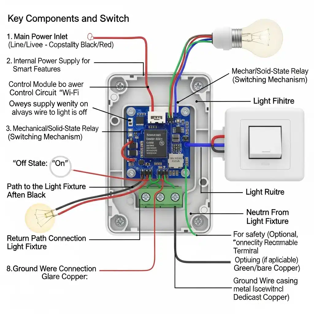
Installing a no neutral smart switch requires a higher degree of precision than replacing a standard mechanical toggle. While a mechanical switch simply acts as a gatekeeper, physically severing the connection, a smart switch is an active load that must remain powered. This fundamental difference dictates specific wiring requirements and troubleshooting steps.
In a standard "switch loop" configuration common in older homes, you will typically find two black wires (or one black and one white wire marked with electrical tape to indicate it is hot) connected to your existing switch. Unlike a mechanical switch, where polarity rarely matters, a smart switch installation requires you to correctly identify the Line (Source/Hot) and the Load (Leg/Switch Leg).
In the absence of a neutral wire (which usually acts as the return path for the control circuit), many no-neutral switches utilize the bare copper or green Ground wire as a reference for zero potential or to dissipate minor EMI (Electromagnetic Interference).
Ensure your metal wall box or the bare copper wire is securely connected to the switch's green lead. If your home utilizes armored cable (BX) or conduit as the ground path, verify continuity between the box and the main panel. A floating ground can cause erratic radio behavior (Zigbee/Z-Wave dropouts) or prevent the switch from initializing.
The most prevalent issue with no-neutral setups is LED "ghosting"—where the bulb glows faintly when turned off—or strobing when turned on.
The Physics of the Problem:
Because there is no neutral wire to return the current used by the smart switch's Wi-Fi or radio chip, the switch effectively "leaks" a tiny amount of current through the Load wire and through the light bulb itself to complete the circuit to the neutral at the fixture.
If the internal resistance of the switch's logic board requires a current $I_{leakage}$, the power dissipated across the bulb when the switch is "off" is defined as:
$$ P_{parasitic} = I_{leakage}^2 \times R_{bulb} $$
Old incandescent bulbs had high resistance and required significant current to glow, so this tiny leakage was invisible. Modern LEDs, however, are highly efficient and have capacitive drivers. Even a minuscule current (often $<5mA$) can charge the LED driver's capacitor until it discharges, causing a flash, or sustain a dim glow.
The Solution: The Bypass Capacitor
If you experience ghosting, you must install a "bypass" or "LUT-MLC" adapter (often included with the switch) at the light fixture—not at the switch. This component is wired in parallel with the light bulb.
Mathematically, the bypass creates a low-impedance path for the leakage current. It ensures that the voltage drop across the LED driver remains below the threshold required to activate the diode:
$$ V_{LED} < V_{threshold} $$
The bypass effectively "shunts" the leakage current around the bulb, allowing the smart switch to stay powered without lighting the fixture.
While many homeowners can handle a straightforward smart switch installation, stop and call a professional if:
* Aluminum Wiring: Your house has dull gray wires (aluminum) instead of copper. Smart switches are generally rated for "CO/ALR" or copper only; connecting them to aluminum without specialized connectors creates a severe fire hazard.
* No Ground: If the box is plastic and contains no ground wire, you cannot safely install most smart switches.
* Multi-Gang Confusion: If you open a box with three or four switches and cannot distinguish which neutrals (if any exist in the bundle) belong to which circuit.
For homeowners facing the "no neutral" limitation, the decision often comes down to a calculated tradeoff between higher upfront hardware costs (premium switches) versus the labor-intensive capital improvement of updating the electrical infrastructure. While having a neutral wire at every gang box is the modern NEC (National Electrical Code) standard, retrofitting an existing finished home to meet this standard is rarely financially viable solely for the purpose of smart lighting.
To understand the cost, one must understand the physical alteration required. In older wiring topologies (specifically the "switch loop"), the power source feeds the ceiling light fixture directly. A single 2-wire cable runs down to the switch to break the "Hot" line.
To add a neutral wire, an electrician cannot simply run a single white wire to the box. They must replace the existing 14/2 or 12/2 NM-B cable (Romex) with a 3-wire assembly (Hot, Neutral, Switch Leg, plus Ground), or re-route the line feed to enter the switch box first. This process involves "fishing" new cabling through finished walls, drilling through fire blocks, and navigating insulation.
Let us define the cost comparison mathematically.
1. The Cost of Rewiring ($C_{rewire}$)
Rewiring requires skilled labor and typically involves drywall restoration. The cost function can be estimated as:
$$ C_{rewire} = N \times (L_{elec} + M_{mat} + R_{wall}) $$
Where:
* $N$ is the number of switch locations.
* $L_{elec}$ is the electrician's labor per drop (typically \$150–\$300 depending on complexity and access).
* $M_{mat}$ is materials (copper cabling, new boxes).
* $R_{wall}$ is the cost of drywall patching, texturing, and painting (often \$50–\$100 per opening).
For a home requiring 20 smart switches, even a conservative estimate of \$200 per drop results in a total infrastructure cost of **\$4,000**.
2. The Cost of Premium Hardware ($C_{hardware}$)
Premium "No Neutral" systems (such as Lutron Caséta) carry a higher unit price than generic Wi-Fi switches but eliminate the labor variable entirely.
$$ C_{hardware} = (N \times P_{switch}) + P_{hub} $$
Where:
* $P_{switch}$ is the price of a no-neutral dimmer (approx. \$50–\$60).
* $P_{hub}$ is the one-time cost of the requisite bridge (approx. \$80).
For the same 20 switches, the hardware cost is approximately:
$$ (20 \times \$60) + \$80 = \$1,280 $$
In this scenario, the hardware route saves approximately \$2,720 and eliminates the downtime and mess associated with construction. The Return on Investment (ROI) for rewiring solely for smart lights is negative.
Exceptions: When Rewiring is Justified
While hardware is the logical choice for 90% of retrofit applications, rewiring is technically advisable if:
1. Knob and Tube Wiring: If your home utilizes pre-1940s knob and tube wiring, the insulation is likely compromised. Insurance requirements may necessitate a full rewire, at which point neutrals should be added.
2. Box Fill Capacity: Older metal device boxes are often small. Crowding them with smart dimmers (which are physically deeper than mechanical switches) may violate box fill calculations defined in NEC 314.16. If the box must be replaced, pulling new wire may be incidental.
3. Ungrounded Circuits: If there is neither a neutral nor a ground wire, safety becomes a primary concern, and circuit modernization is highly recommended.
No. Absolutely not. This is known as a "bootleg neutral," and while it may physically complete the circuit and allow the device to power up, it is a severe safety hazard and a violation of the National Electrical Code (NEC Article 200.6 and 250.6).
In an alternating current (AC) system, the neutral wire (technically the Grounded Conductor) serves as the low-impedance return path for the current consumed by the load. The bare copper or green wire (the Equipment Grounding Conductor) is a non-current-carrying safety bond designed to divert current to earth only during a fault condition (such as a short circuit) to trip the breaker.
If you wire the neutral terminal of a smart switch to the ground wire, you are forcing the return current ($I_{return}$) to flow through the grounding system of your home. Because the ground wire has non-zero resistance ($R_{ground}$), Ohm’s Law dictates that a voltage potential will develop across that wire:
$$ V_{drop} = I_{return} \times R_{ground} $$
This creates an energized potential on every metal surface connected to that ground loop—including the screws on your light switch faceplate, the metal casing of your appliances, and plumbing fixtures. This creates a high risk of electrocution. If you lack a neutral, you must use a specific no-neutral switch or pull a new standard 14/3 or 12/3 Romex line.
Standard mechanical dimmers (rheostats or basic TRIAC-based rotary knobs) do not require a neutral wire because they operate purely in series with the load, mechanically varying the resistance or chopping the AC phase. However, smart dimmers generally require a neutral to power their internal Wi-Fi/Zigbee/Z-Wave radios.
"No-neutral" smart dimmers bypass this requirement by utilizing parasitic power extraction (power stealing). They are designed with high internal impedance to allow a minute leakage current to flow through the load even when the switch is theoretically "off." The power consumption of the switch logic ($P_{logic}$) is maintained by allowing a sub-luminous current ($I_{leakage}$) through the filament or LED driver:
$$ I_{leakage} = \frac{P_{logic}}{V_{line}} $$
The challenge arises with low-wattage LED bulbs. If the LED driver's input capacitance charges up from this leakage current, the bulb may flash periodically or glow faintly (ghosting). This occurs because the $I_{leakage}$ required by the switch exceeds the threshold of the LED driver. This is why many no-neutral dimmers require a resistive bypass adapter wired in parallel at the fixture to shunt this current.
Buzzing is typically caused by magnetostriction in the inductive components of the dimmer or the LED driver, or by piezoelectric effects in the capacitors, usually resulting from mismatched dimming methods.
Most no-neutral smart switches use Phase-Cut Dimming to regulate brightness. They rapidly switch the AC sine wave on and off 120 times per second (for 60Hz power).
* Leading Edge (Forward Phase): Cuts the front of the sine wave. This creates a massive spike in voltage change over time ($\frac{dV}{dt}$) at the moment of activation.
* Trailing Edge (Reverse Phase): Cuts the end of the sine wave. This is generally gentler on modern electronics.
If a Leading Edge dimmer is used with an LED driver designed for Trailing Edge input (or vice versa), the rapid rise time of the voltage causes the ferrous core of the inductors (chokes) inside the dimmer or bulb to physically expand and contract at the frequency of the AC mains (60Hz) or its harmonics (120Hz, 240Hz). This physical vibration moves air, which you perceive as an audible buzz. To eliminate this, ensure your smart switch supports ELV (Electronic Low Voltage) dimming, which utilizes trailing edge MOS-FET technology rather than TRIACs.