In the domain of electrical engineering, a ballast serves as the critical control gear for gas discharge lamps, including fluorescent and High-Intensity Discharge (HID) lighting. Unlike incandescent bulbs, which utilize a resistive filament that naturally regulates current via thermal equilibrium, gas discharge lamps exhibit negative differential resistance. As the gas within the arc tube ionizes, the internal resistance drops significantly. If connected directly to a constant voltage source, the current would rise uncontrollably according to Ohm’s Law, leading to the catastrophic destruction of the lamp.
The primary function of the ballast is to provide the necessary positive impedance to stabilize the circuit. It strictly limits the current flowing through the lamp to the manufacturer’s specified operational parameters. Mathematically, the ballast ensures that the total circuit impedance ($Z_{total}$) restricts the current ($I$) such that:
$$ I = \frac{V_{source} - V_{lamp}}{Z_{ballast}} $$
(Note: In AC circuits, this calculation involves vector subtraction due to phase angles, not simple algebraic subtraction.)
Beyond current regulation, the ballast facilitates the ignition sequence. Gas discharge lamps require a high initial voltage—often significantly higher than the line voltage (120V or 277V)—to establish the dielectric breakdown of the gas mixture and strike the electrical arc. Once the arc is established, the ballast rapidly reduces the voltage to the lower sustaining level required to maintain ionization.
Traditional magnetic ballasts operate on the principle of inductive reactance. They consist of copper windings around a ferromagnetic core, functioning as a large inductor. The inductive reactance ($X_L$) is determined by the line frequency ($f$) and the inductance ($L$):
$$ X_L = 2\pi f L $$
Because magnetic ballasts operate at the standard line frequency (60 Hz in North America), they are physically heavy and prone to audible noise caused by magnetostriction—the physical deformation of the core laminations reacting to the alternating magnetic field. Furthermore, the 60 Hz operation can produce a perceptible stroboscopic effect (flicker) and is generally less efficient due to heat loss in the copper windings and core hysteresis.
Modern lighting systems predominantly utilize electronic ballasts, which employ solid-state electronic components to regulate current. The topology typically involves a rectifier to convert the AC input to DC, followed by an inverter that drives the lamp at a much higher frequency, typically between $20\text{ kHz}$ and $60\text{ kHz}$.
This high-frequency operation offers significant technical advantages:
1. Increased Efficacy: The excitation of phosphors in fluorescent tubes is more efficient at higher frequencies, resulting in greater lumen output per watt.
2. Elimination of Flicker: The cycling rate is far beyond the threshold of human visual perception.
3. Silence: Operating frequencies are ultrasonic, eliminating the 60 Hz hum associated with magnetic vibration.
4. Power Factor Correction: Advanced electronic ballasts include active power factor correction (PFC) circuitry, keeping the power factor close to $1.0$, which minimizes harmonic distortion on the electrical grid.
Understanding the distinction between these two architectures is vital for troubleshooting. While a magnetic ballast often fails gradually with symptoms like loud buzzing or excessive heat, electronic ballasts tend to fail abruptly due to the breakdown of capacitors or transistors on the printed circuit board (PCB).
The most immediate indicators of ballast failure manifest through sensory irregularities—specifically auditory disturbances and visual inconsistencies. A lighting ballast functions as a current-limiting device and a voltage transformer; when its internal components degrade, the regulation of the electrical arc within the fluorescent or HID tube becomes unstable.
One of the earliest signs of degradation in older magnetic ballasts is fluorescent light humming and flickering. The audible humming results from a phenomenon known as magnetostriction. Inside a magnetic ballast, the core consists of laminated steel plates. As the potting compound (the insulating tar-like substance) dries out due to heat cycles, these laminations begin to vibrate against one another at twice the supply frequency (usually $120\text{Hz}$ in the US).
In modern electronic ballasts, flickering usually indicates the failure of the electrolytic capacitors in the power factor correction stage. When these capacitors fail to smooth the rectified DC voltage, a significant "ripple" voltage is introduced to the output. This causes the arc current to modulate rapidly, resulting in a visible strobing effect. If the voltage drops below the minimum threshold required to sustain the arc plasma, the light will extinguish and attempt to re-strike repeatedly.
Ballasts are responsible for providing a high initial voltage spike ($V_{strike}$) to ionize the mercury vapor inside the tube, reducing the gas resistance so current can flow. A clear indicator of failure occurs when fluorescent lights slow to turn on ballast components are unable to generate this necessary potential difference quickly.
Technically, this is often a failure of the start capacitor or a degradation of the rapid-start windings. The cathodes may glow (indicating filament voltage is present), but the ballast cannot produce the high-voltage kick required to bridge the gap. The time constant $\tau$ for the startup circuit increases, causing significant delays. In cold environments, a failing ballast will struggle exponentially more, as lower temperatures reduce the vapor pressure of the mercury, requiring an even higher $V_{strike}$ that the compromised unit cannot deliver.
A frequent point of confusion during diagnosis is the relationship between the ballast and light intensity. To answer the technical query—does a bad ballast cause dim lights—the answer is a definitive yes, though the mechanism differs from bulb aging.
While a dying bulb becomes dim due to the depletion of emissive coating on the electrodes or phosphor degradation, a bad ballast causes dimness through improper current regulation. The ballast must act as a high impedance load to counteract the "negative resistance" characteristics of the discharge arc. If the internal impedance of the ballast increases due to component fatigue, the operating current ($I_{op}$) delivered to the lamp decreases. Since the luminous flux ($\Phi$) is roughly proportional to the power consumed by the arc ($P_{arc} = V_{arc} \cdot I_{op}$), a drop in current results in a proportional drop in brightness. Furthermore, in electronic ballasts, if the switching frequency drifts away from the design resonance, the power transfer efficiency drops, leading to visibly lower lumen output and potential uneven lighting across the length of the tube.
Before attempting to visually inspect the internal components of any luminaire, rigid safety protocols must be observed. Ensure the circuit is de-energized at the breaker panel and verify the absence of voltage using a non-contact voltage tester or a multimeter. Once the fixture is isolated, remove the diffuser (lens) and the ballast cover (often called the raceway) to expose the ballast unit.
When determining what does a bad ballast look like, one must look beyond simple cosmetic wear to identify structural integrity failures caused by thermal runaway or component breakdown. A healthy ballast should present as a clean, rectangular brick—typically encased in painted steel or aluminum—with flat surfaces and intact, legible labeling. Deviations from this geometric standard are primary indicators of failure.
Ballasts are rated for a specific maximum case temperature, denoted as $T_c$, typically ranging between $70^\circ\text{C}$ and $90^\circ\text{C}$. Operating continuously above this threshold degrades the internal insulation. Visually, this manifests as:
For older magnetic ballasts and some heavy-duty HID units, the internal core and coil transformer are submerged in a potting compound—an asphalt-based material designed to dissipate heat and dampen acoustic vibration.
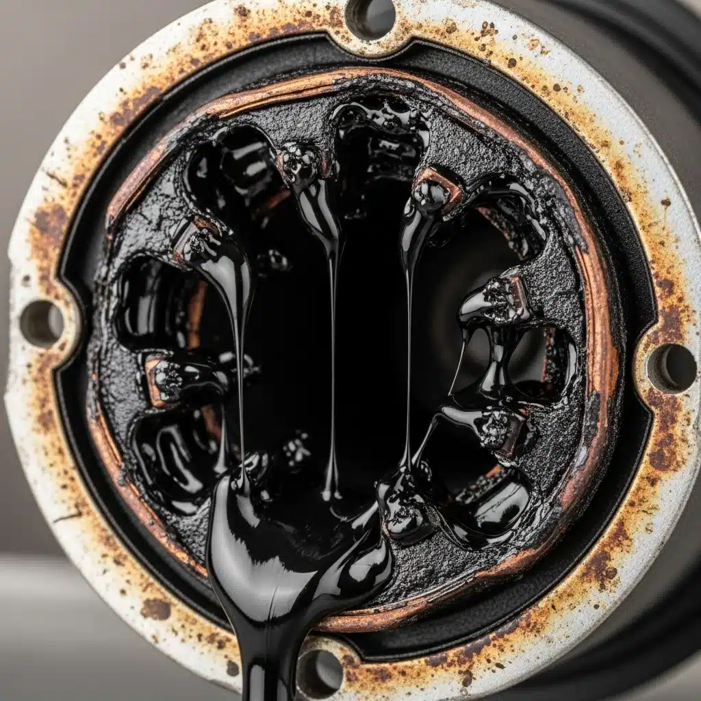
One of the most definitive indicators of a critical fault is the visual signs of ballast failure leaking. When a ballast overheats significantly, this potting material changes phase from a solid or semi-solid state to a liquid. Because the internal volume is sealed, the expanding, liquefied compound forces its way out through wire exits or seams in the metal casing.
Inspect the fixture for the following:
1. Black Tar: The leaking substance resembles black tar or heavy crude oil. It may drip onto the bulb, the diffuser, or pool in the bottom of the fixture housing.
2. Stalactites: In severe cases, the cooling compound may form solidified droplets hanging from the ballast body.
3. Oil Sheen: Early stages of leakage may appear as a greasy film or oil residue coating the wires entering the ballast.
If any leakage is observed, the ballast is considered hazardous. The compromised insulation creates a high risk of short circuits to the ground, potentially energizing the metal fixture housing. Do not attempt to clean and reuse a leaking unit; immediate replacement is required.

Before initiating the invasive process of disconnecting wiring or purchasing a replacement ballast, an efficient technician must first rule out the consumable component: the lamp itself. Because ballasts and bulbs function as a coupled inductive-resistive circuit, a failure in one often mimics a failure in the other. Distinguishing between bad ballast vs bad bulb symptoms requires a systematic elimination process to avoid unnecessary capital expenditure and labor.
The first step is a non-contact visual assessment of the fluorescent tube or HID lamp. Fluorescent tubes rely on thermionic emission from tungsten filaments coated in an emissive paste (usually barium, strontium, and calcium oxides). As the bulb ages, this emissive coating sputters off the filament and deposits onto the glass wall.
If visual signs are inconclusive, the most definitive method for isolating the fault is the "Known Good" swap test. This applies logic similar to differential troubleshooting in circuit design.
Method A: The "Known Good" Source (Preferred)
1. Remove the suspect bulb from the malfunctioning fixture.
2. Install a brand-new bulb or a bulb verified to work in another fixture.
3. Result Analysis:
* If the fixture ignites immediately and operates without flicker: The Bulb was the fault.
* If the new bulb fails to strike, flickers, or glows dimly: The Ballast is likely the fault.
Method B: The "Suspect" Transfer
1. Remove the suspect bulb.
2. Install it into a fixture known to be functioning correctly.
3. Result Analysis:
* If the bulb works in the new fixture: The original Ballast is faulty.
* If the bulb fails in the working fixture: The Bulb is faulty.
While the swap test is definitive, understanding the technical nuance of bad ballast vs bad bulb symptoms helps in rapid diagnosis without tools.
Mathematically, the ballast acts as a current limiter. If the ballast's internal impedance ($Z$) drops due to a shorted winding, the current ($I$) flowing to the bulb increases according to a variation of Ohm's Law for AC circuits:
$$ I = \frac{V}{Z} $$
Where $V$ is the supply voltage. If the ballast allows $I$ to exceed the bulb's design specifications, a new bulb will burn out rapidly. Therefore, if a fixture destroys new bulbs within days, the diagnosis is a bad ballast over-driving the lamp, not a defect in the bulbs themselves.
While the fundamental function of a ballast—limiting current to the load—remains consistent across gas-discharge lighting, the failure modes differ significantly between Low-Pressure Mercury (fluorescent) and High-Intensity Discharge (HID) systems. Diagnosing these requires distinguishing between the specific operational characteristics of the arc tube physics involved.
The signs of bad fluorescent ballast performance often manifest as visual instabilities known as striations or spiraling, particularly in T8 and T12 linear tubes. Unlike a simple burnout, a failing fluorescent ballast may struggle to maintain the requisite frequency or heater voltage, leading to a phenomenon often described as "shimmering."
In older magnetic ballasts operating at line frequency ($60\text{ Hz}$), failure is often audible (humming) due to the delamination of the transformer core. However, in modern electronic ballasts, which operate at high frequencies ($20\text{ kHz} - 60\text{ kHz}$), the symptoms are visual. If the ballast fails to regulate the current crest factor—the ratio of peak current to RMS current ($I_{peak} / I_{rms}$)—the arc becomes unstable. A crest factor exceeding $1.7$ can cause the arc to wobble or swirl inside the glass tube.
Furthermore, strictly for Rapid Start or Programmed Start ballasts, the inability to provide continuous low-voltage heating ($3.5\text{V} - 4.0\text{V}$) to the cathodes results in darkened ends on the tubes. If new tubes blacken within days of installation, the ballast is likely overdriving the current or failing to heat the filaments, causing rapid sputtering of the emissive coating.
The diagnostic approach changes for High-Intensity Discharge lamps due to the high internal pressures and temperatures required for operation. The most definitive symptoms of a failing HID ballast involve "cycling" and chromatic shifts.
Cycling is a condition where the lamp strikes, warms up to full brightness, extinguishes, cools down, and then strikes again. While this can indicate an end-of-life lamp, it is frequently caused by a ballast that can no longer sustain the operating voltage required by a hot arc. As an HID lamp heats up, the internal pressure ($P$) increases, which increases the voltage drop ($V_{arc}$) across the electrodes. The ballast must maintain an Open Circuit Voltage ($OCV$) significantly higher than the lamp’s operating voltage to sustain the arc.
$$ V_{ballast\_output} > V_{arc(hot)} $$
If the ballast's transformer coils have degraded or shorted, the output voltage drops. Once the lamp reaches operating temperature, the required $V_{arc}$ exceeds the ballast's output capacity, breaking the circuit. The lamp must then cool until internal pressure decreases enough for the ballast to re-strike the arc.
Color Shifting is particularly prevalent in Metal Halide systems. As the ballast capacitors age, the power regulation drifts. If a ballast under-drives a Metal Halide lamp, the arc tube does not reach the thermodynamic equilibrium necessary to vaporize the halide salts correctly. This results in a distinctive color shift—often turning the light pink or dim green—indicating that the chemical reaction is incomplete due to insufficient power delivery. Additionally, for High-Pressure Sodium (HPS) and Pulse Start Metal Halide units, failure of the ignitor component (a sub-circuit of the ballast assembly) will prevent the generation of the high-voltage pulse ($3\text{ kV} - 5\text{ kV}$) required to ionize the gas initially, resulting in a system that hums but never produces light.
Among the various symptoms of lighting failure, the detection of a distinct, acrid odor is the most urgent indicator of catastrophic component failure. While flickering or buzzing indicates electrical instability, a strong burning smell from light fixture bad ballast signifies thermal runaway and presents an immediate fire hazard. This olfactory warning is typically caused by the physical degradation of internal insulation and chemical compounds under extreme heat.
Ballasts are designed to regulate voltage and limit current. However, as internal components age—specifically the electrolytic capacitors in electronic ballasts or the copper windings in magnetic ballasts—internal resistance or leakage current can increase. According to Joule’s First Law, the power dissipated as heat ($P$) is proportional to the square of the current ($I$) flowing through the resistance ($R$):
$$ P_{heat} = I^2 \cdot R $$
In a failing ballast, dielectric breakdown between the windings causes short circuits. This effectively lowers the impedance of the coil, causing a surge in current ($I$), which exponentially increases the heat generation ($P_{heat}$). If the rate of heat generation exceeds the ballast's thermal dissipation capacity, the internal temperature rises uncontrollably.
The specific "flavor" of the smell often helps diagnose the type of failure:
Most modern ballasts are "Class P" rated, meaning they contain an internal thermal protector that disconnects the power supply if the case temperature exceeds a specific threshold (typically around $105^\circ\text{C}$). However, this safety feature can lead to "thermal cycling." The ballast overheats, the switch trips (light turns off), the ballast cools, the switch resets (light turns on), and the cycle repeats. Each cycle degrades the insulation further. If the thermal protector fuses in the "closed" position, or if the ballast is an older non-Class P model, the temperature will continue to rise until combustion occurs.
If you detect a burning smell from light fixture bad ballast, follow these steps immediately to mitigate fire risk:

When visual inspections reveal no obvious leaking potting compound or swollen casings, electrical validation is required to confirm a diagnosis. Understanding how to test a light ballast with a multimeter allows you to verify the integrity of the internal copper windings and electronic components. This process moves beyond symptom observation to definitive failure analysis using resistance and continuity testing.
Before exposing internal wiring, you must adhere to strict electrical safety protocols. Light ballasts, particularly older magnetic models and High-Intensity Discharge (HID) units, operate at voltages significantly higher than the standard $120V$ or $277V$ line voltage.
To test the internal windings of the ballast, you are testing for electrical continuity (a complete path for current flow) and resistance.
The primary side receives the line voltage. Locate the input wires, typically Black (Hot) and White (Neutral). Cut the wires about three inches from the ballast to isolate it from the building's circuit (or disconnect the wire nuts).
The secondary side outputs voltage to the lamp sockets. These are usually Blue, Red, or Yellow wires.
The distinction between a functional and failed unit lies in the multimeter display:
Once a ballast has been diagnosed as defective via visual inspection or multimeter testing, the facility manager or engineer faces a critical decision: perform a direct component replacement or retrofit the fixture to LED technology. This choice relies on a cost-benefit analysis weighing immediate materials costs against long-term operational efficiency, thermal management, and maintenance cycles.
Replacing the ballast with an equivalent unit (typically an electronic ballast for T8/T5 systems) is often viewed as the path of least resistance. This approach preserves the existing UL listing of the fixture without modification and utilizes the current wiring harness and socket configuration. However, this is increasingly considered a stop-gap measure. When selecting a replacement ballast, one must match the Ballast Factor (BF)—a multiplier usually ranging from $0.77$ to $1.18$—to ensure the lumen output remains consistent with the original design. A mismatch in BF or input voltage (e.g., installing a 120V ballast on a 277V circuit) will result in immediate failure or drastically reduced lamp life.
The industry standard has shifted toward retrofitting fixtures with Type B (Ballast Bypass) LED tubes. In this configuration, the faulty ballast is physically removed or disconnected, and line voltage ($120\text{V}$–$277\text{V}$ AC) is wired directly to the G13 "tombstone" sockets.
This approach offers distinct engineering advantages:
1. Elimination of Failure Points: The ballast is the most common failure point in fluorescent fixtures. Removing it simplifies the circuit topology.
2. Thermal Load Reduction: Ballasts generate significant waste heat. Removing them lowers the internal temperature of the fixture, reducing stress on wire insulation and polycarbonate lenses.
3. Luminous Efficacy: LEDs provide a higher lumen-per-watt ratio and better directionality (directional throw vs. omnidirectional fluorescent waste).
Technical Consideration regarding Sockets:
When converting to Type B LEDs, the technician must identify if the existing sockets are shunted or non-shunted.
* Shunted sockets (common in Instant Start ballasts) have internal jumper wires connecting the two contact pins.
* Non-shunted sockets (common in Rapid Start ballasts) have independent contacts.
For single-ended power LED tubes, non-shunted sockets are required. If the existing fixture utilizes shunted sockets, they must be replaced, slightly increasing the labor time for the retrofit.
The decision often comes down to the Return on Investment (ROI) based on energy differential and maintenance avoidance.
The annual energy savings ($S_{annual}$) can be modeled as:
$$ S_{annual} = \frac{(P_{sys\_fluor} - P_{sys\_LED}) \times H_{op}}{1000} \times R_{elec} $$
Where:
* $P_{sys\_fluor}$ is the total system wattage of the fluorescent fixture (lamps + ballast overhead). For a 4-lamp T8 fixture, this is typically $\approx 112\text{W}$.
* $P_{sys\_LED}$ is the total wattage of the LED retrofit. For 4 Type B LED tubes (approx. $15\text{W}$ each), this is $\approx 60\text{W}$.
* $H_{op}$ is the annual operating hours.
* $R_{elec}$ is the utility rate per kWh.
Additionally, one must consider the Lifespan Differential. Fluorescent tubes typically offer a service life of 20,000 to 30,000 hours, with lumen depreciation occurring rapidly after 40% of that life. LED tubes are generally rated for $50,000+$ hours ($L_{70}$), meaning they maintain 70% of their initial brightness at the 50,000-hour mark.
Conclusion: If the fixture housing is in good physical condition (no rust, intact lens), bypassing the ballast for a Type B LED retrofit is almost universally the superior engineering choice. It decouples the light source from legacy power regulation hardware, resulting in a system that is electrically simpler and thermally more efficient.
The Mean Time Between Failures (MTBF) for modern electronic ballasts typically ranges from 50,000 to 60,000 hours, assuming operation at the manufacturer's specified maximum case temperature ($T_c$), usually $75^{\circ}C$ or $90^{\circ}C$. Magnetic ballasts, while less efficient, are simpler devices consisting of copper windings and a ferrous core, often lasting upwards of 75,000 hours or 20+ years.
Failure is almost exclusively a function of thermal stress and input voltage quality. Electronic ballasts rely on electrolytic capacitors to smooth the DC bus voltage. These components are sensitive to heat. Following the Arrhenius equation regarding chemical reaction rates, a general rule of thumb for capacitor life ($L$) concerning temperature is:
$$ L_{actual} = L_{rated} \times 2^{\frac{T_{rated} - T_{actual}}{10}} $$
This implies that for every $10^{\circ}C$ rise in operating temperature above the rated $T_c$, the ballast's life expectancy is halved. Conversely, operating the ballast $10^{\circ}C$ cooler than its rating can double its lifespan. Aside from heat, transient voltage spikes can cause dielectric breakdown in the MOSFETs or diodes, leading to immediate catastrophic failure.
Cross-compatibility is strictly governed by electrical parameters and ANSI standards; physical fitment does not guarantee electrical compatibility.
Polychlorinated Biphenyls (PCBs) were commonly used as a dielectric fluid and coolant in the capacitors of magnetic ballasts manufactured prior to 1979. PCBs are persistent organic pollutants and classified as a known carcinogen.
Identification:
* Date of Manufacture: Any ballast manufactured before January 1, 1979, should be presumed to contain PCBs unless stated otherwise.
* Labeling: Following the Toxic Substances Control Act (TSCA) ban, manufacturers were required to label non-PCB ballasts with the text "No PCBs". If a magnetic ballast lacks this specific label, treat it as hazardous waste.
* Physical Signs: Leaking ballasts containing PCBs will exude a clear to yellow oily liquid, distinct from the black tar-like potting compound used for noise suppression (though the potting compound may also be contaminated).
Disposal Protocols:
Under the Comprehensive Environmental Response, Compensation, and Liability Act (CERCLA), ballasts containing PCBs cannot be disposed of in standard municipal solid waste streams. They must be incinerated at high temperatures or disposed of in specific chemical waste landfills (TSCA-approved facilities). When removing these units, technicians must wear nitrile gloves and eye protection to prevent dermal absorption of the dielectric fluid. Ruptured ballasts require immediate containment and hazardous material cleanup procedures.